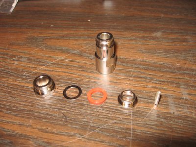
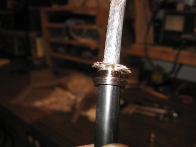
It's a good idea to put a piece of tape down the line about a couple of feet. This will keep the parts from sliding to far away and getting dirty on the floor/ground. Now, install the nut (noting correct direction), then the ring, then o-ring. Strip the line back about 3 inches. Later, when more proficient, you can cut less back. Strip only the outer (normally black) PVC insulation and leave the center dialectic intact at this point. Now, install the shield piece. (noting correct direction). When you install the piece in the correct direction you'll notice the o-ring will seat nicely on it's under side.
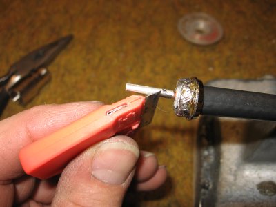
Next, lay out the shielding perpendicular to the line, against the top of the shield piece. Using small scissors trim the excessive braid around the shield piece. There should be just enough braid to lay down the side of the piece, but not go beyond the other edge.
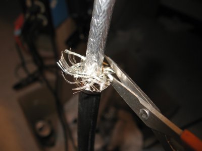
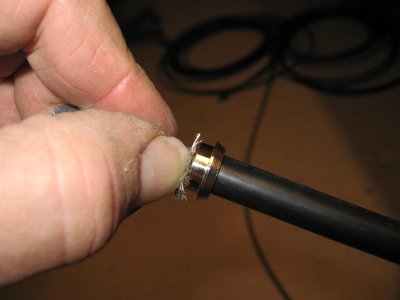
Using your fingernail, gently push over the braid in small steps. This will avoid the strands separating from the group.
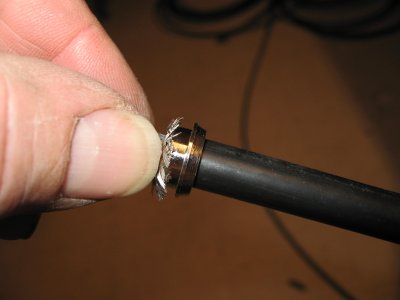
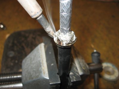
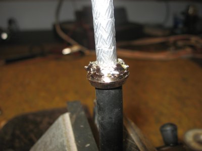
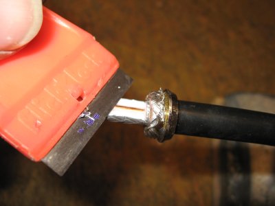
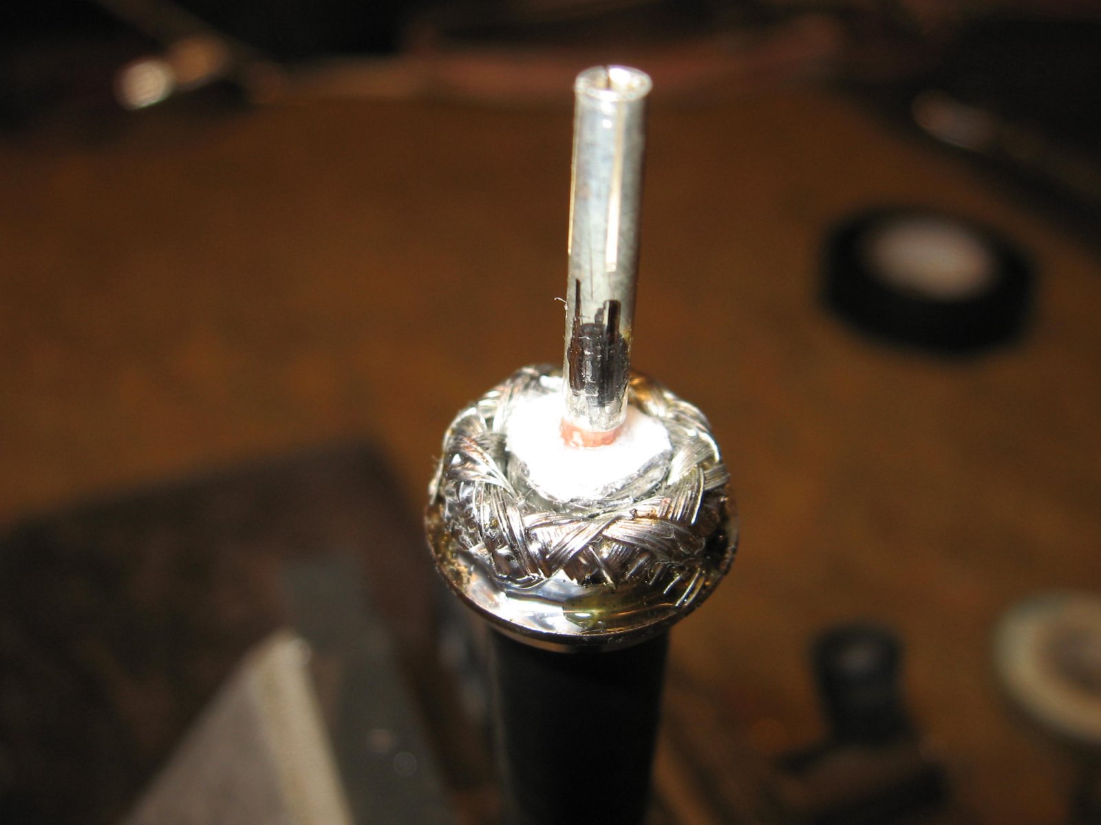
You should end up with the braid nicely laid over the shield's surfaces. This is important for a good, close solder connection to the piece. Lightly apply solder all the way around the braid. At this point you don't need to heat up the shield piece. It will look like the center picture, rough and ready for heat. Now, apply the last part of the solder, while allowing the heat to transfer the shield piece. Quickly touch about three sides with the iron, each time the solder will melt and flow into the piece quicker, so be ready for that, to avoid excessive solder running over the top of the piece. The right picture shows you'll end up with a nice, neat, well-soldered shield connection, that is much stronger than a conventional press-braid connection.

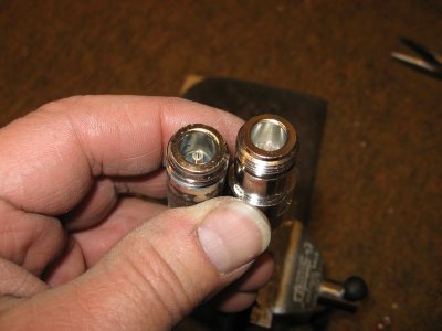
Next, razor cut the center dialectic material from the center line's conductor. Leave a little space from the edge of the braid to where you start the cut. Look inside the connector's body for that little "lip" for the proper sizing. This will help guide and hold the center conductor, keeping it away from the outer shield part of the connector's body. Run the razor around the material, being careful not to cut into the line's center conductor very much; a tiny "nick" is ok. You should be able to pull the material off, with a slight twist action, in one direction only. The center conductor is copper, which is forgiving, up to a point, so don't weaken it with aggressive pulling or twisting. Some brands of lines have difficult material. The Crushcraft "Signals" dialectic is hard enough to permit easy removal. The Times Microwave "LMR-400" is not so easy, because it's soft and tends to stick to the center conductor. A way around this is to slice down the side with the razor in a few angles to break it free. Then clean the conductor of the material. It's also a good idea to shine up the copper with a mini-wire brush, such as with a dremmel tool. Because the shield is soldered you have the advantage of being able to insert the connector's body to check on pin position. Plus, easy inspection is possible at a later date. With conventional (press only) it's a small nightmare to re-dress the shielding when taking the housing back off. Use a commercially made connector or adaptor for comparison. If the pin is too far out it will bind (and maybe break) when plugging into the mating connector. If it's (way) too short it won't make a connection with the mate. Solder the pin.
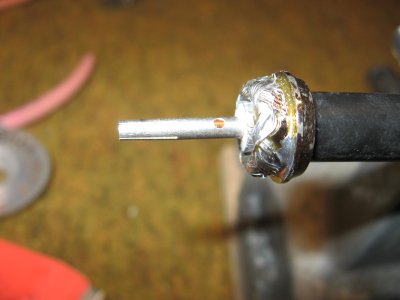
If you get some solder outside the pin this will cause restriction when installing the connector body. You can either remove (and smooth) with a file or razor. The right picture's example shows the area ready for final assemble. The braid is nicely laid out, embedded in solder, while the pin is the correct length, straight and has sufficient solder to bond the inside of the pin to the outside copper center conductor.
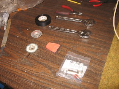
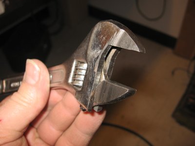
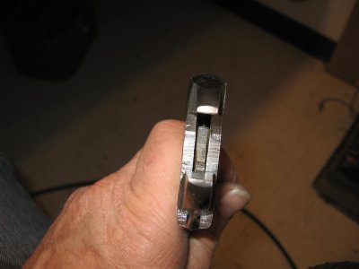
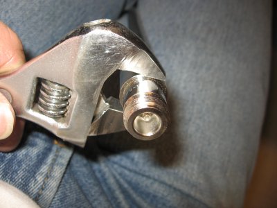
Run the nut, ring and gasket up to the rear of the connector's housing and push and twist the nut to get it started on the housing's inside threads. A word or two on tightening the nut. The body has two flat areas to facilitate a wrench. The approximate wrench size for this is 18mm. Metric wrench sizes normally jump in size from 17 to 19mm. Since this size is hard to fine most will try to use pliers, which can make some scratches on the body's surface. Another approach is to use an adjustable wrench. However, most wrenches are too wide for this. While the female's body design is not a factor (no pun intended) the male does have a space issue, when using a conventional wrench. To address this problem the Author came up with a cool idea. Notice something strange about this wrench? Yes, it's modified with a narrow "bit" so it can fit nicely on the housing of the connector.
The second wrench is to tighten the nut. Snug it down, but don't get too aggressive; remember you have plenty of torque with a wrench. When done, you should be able to play and pull (gently) on the connector without anything coming loose. Also, you can now remove that temporary piece of tape you installed a couple feet down from the end of the cable.
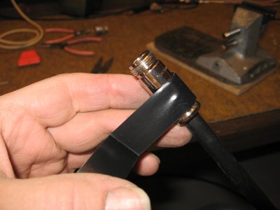
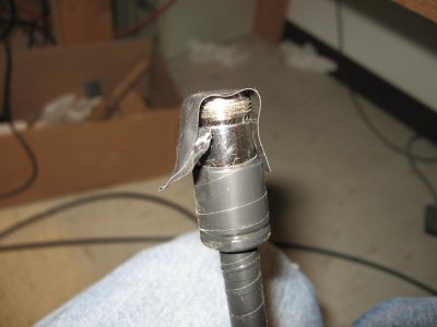
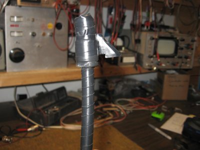
Taping up connectors is not a favorite task while on the tower, especially in fowl weather. To minimize this task, tape most of the connector's body and coax area. Leave just the threads, for plugging the connector.
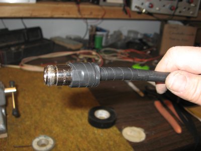
While in transport and installation the connector may be subject to contamination, just as dropping it into the dirt or snow. Make a temporary "seal" with another layer of tape, but this time leave a "handle" at the end of the tape to allow easy removal during tower installation and plugging into another connector. Then complete sealing the entire exposed area.
![[SRG home Direction]](images/srghome.gif)