Introduction
The Midland radio makes a fair repeater, or a simple link radio. Unlike the Motorola channel elements, just the crystal holder (metal case) uses frequency control and is plugged in.
Acronyms, Definitions, Radio System Operation and Theory:
Amateur Radio is to develop the art of radio and improving operating practices. This can set a good example for others, including the commercial industry, to what amateur radio system(s) are capable of doing to provide public service communications in time of need. This includes the technical side, to produce good operating repeater systems. We will start with very basic theory. Two-way radio systems send intelligence (voice, data, etc.) by modulating the originating transmitter and decoding (detecting) this modulation at the far end receiver back to something usable to be understood. How well this is understood depends greatly on how well the system is set up. Anyone can make a system work; "throw" it together and it will work, somewhat. This discussion promotes a better way. For one, Technician organization and discipline is necessary. Plan on what you want to do for a system design and stick to it. Force yourself to keep good practices. One method to keep the guesswork out of working on a system is to establish level references. Some call these "benchmarks", or "baselines".
Most 2-way systems use the audio portion (AF/VF) to modulate them. A typical (commercial) system uses 300 Hz ~ 3 KHz for modulation and detection for a voice "channel". For this discussion, frequency modulation and level is somewhat different. While old Amateur methods used linear (volts, watts, etc) units of measure, most figures here mentioned are in logarithmic units. Once accustomed, it's easier to see the entire picture this way, when designing a system, checking frequency response, or even doing path analysis and keeps the guesswork out of trouble shooting a subtle level problem.
References can be expressed in a few acronyms. Test Tone level (TTL) into a two-way VHF/UHF transmitter or out of a VHF/UHF receiver is referenced to a test tone frequency of 1 KHz, of %100 system modulation. For this standard, that is +,- 5 KHz deviation. Other areas and services have different bandwidths, such as in P-25 systems. A Test Level Point, (TLP) refers to a measurement point, on equipment, for a system, in reference to Test Tone Level (TTL). TLP provides easy reference to any parts of the system for measurement and alignment. 0 dbm is referenced to 1 milliwatt at 600 ohm impedance. Therefore, a transmitter AF input with a TLP of 0 dbm, with a Test Tone Level of 0 dbm tone input, would fully modulate the system. A far end receiver with the same TLP would output a 0 dbm tone as well. A 6 db drop in (voltage) level would reduce the modulation in half, and so on. In general, for these standards, levels are stated in transmit-receive (Tx-Rx) order. Therefore, an audio (VF) "drop" TLP of 0/0 would mean a Tx TLP of 0dbm, Rx TLP of 0dbm. Sometimes operating levels are not at TLP. To avoid technician confusion two sets of numbers are sometimes used in diagrams and on the physical equipment. Figures in parenthesis are the TLPs. Non-parenthesis figures are operating levels, and, as mentioned, may be at a different levels from the TLPs.
Long haul RF links are made of several transmitted and received signals. Each time this occurs some reduction in signal quality happens. Stock two-way radios are designed for single path operation, with it's own pre-emphasis, deviation limiting (clipping) and receiver de-emphasis, and "forgiving" squelch operation. For multiple links, these stock radios can add gross problems, such as excessive distortion, audio frequency response being very poor and very long squelch bursts. All these conditions will cause a system to operate very badly and be rather annoying and fatiguing to listen to. These conditions can be corrected, and is done so in all SRG systems.
For the transmitter condition, the mic input is not used, rather, a F.M. section is built to directly modulate the transmitter to provide flat response Each time you limit deviation for each hop will add more distortion. To correct this condition, only limit the modulation at one point, such as the system's controller. This is why the links should not be limited, rather passively 1:1. If you do have to limit, one option would be to set the system limit at 6 KHz and let the system user's transmitters limit at 5 KHz deviation. Passive mode requires system management and user responsibility. This may require some enforcement on the user's part. (There are other circuits to "punish" over modulated users which is beyond the scope of this documentation.)
For the receiver's audio frequency response condition, take each receiver audio off the discriminator. All receiver's discriminators should have great low end response, however, (due to IF filtering restraints) the top end always rolls off too soon. The (before mentioned) audio boards have circuitry to equalize the higher end to extend the response.
For the long squelch burst condition, some theory is needed to be discussed. FM receivers have large IF gain. At the discriminator there is plenty of noise available during signal absence. This noise can be filtered to the top end (i.e.,8-10 KHz), amplified, rectified and DC amplified to usable DC levels. This is known as a noise operated squelch, used on every 2-way radio, and "scanner" today. A signal into the receiver will "quite" the discriminator audio output, which changes the DC levels in the squelch circuit and turns on the audio amplifier to drive the local speaker for listening. It also can be used to operate a link board, and finally, to key an associated transmitter, thus making a repeater. More commonly known as "COS", or Carrier Operated Squelch. Some use the term "COR" (Carrier Operated Relay) which came from the old tube radio days. Both are the same function.
Stock radio receivers have squelch constants (time for squelch to close and mute the audio path) designed for both fixed (base station) and mobile (moving station) signals, therefore, a fairly long(200 msec.) time for squelch close. This is noticed by a burst of laud noise at the end of a received transmission. For a single site this is tolerable, however, for multiple links (hops) this can quickly add up to something annoying to listen to. It also slows down switching paths, causing user frustration. For links this problem can be easily corrected by lowering the R/C constants in the squelch circuits. To shorten the squelch burst the capacitors in several areas of the squelch rectifier area can be reduced. This requires some careful selection. If they are too low the circuits will be unstable. Links are not intended to receive mobile (moving) signals. Therefore, this modification will be transparent to fixed (links) station use, which should be full quieting, strong signals. Only multiple "clicks" would be heard with this modification. The remote user receivers will still have "stock" squelch constants, therefore, will provide for moving (mobile) signal changes, plus "cover up" the multiple link "clicks". The result will sound like a simple, small, single site system. The values are discussed later.
Some History
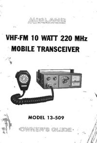
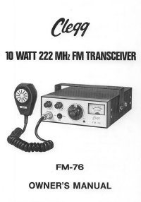
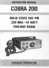
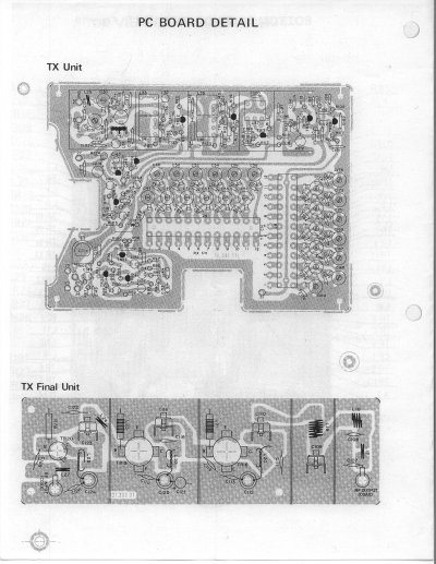
It's suspected these radio were made in the '80's in preparation of the 1 1/4 Meter Amateur band of 220-225 MHz being lost and turned over to "CB". Thus, a cheap crystal controlled radios were built by about three Japanese manufactures, Midland, Clegg and Cobra. Just about all the electronics inside the radio of any of these brands are the same; the only basic difference is the appearance of the case and front panel. The Midland 13-509's had that ugly brown case, with a plastic from panel, while the Clegg FM-76 and the Cobra 200's had a black colored case. All the cases split in the center, top and bottom for the unit. They used a 3-pin mic connector. Some of the mic's were 500 ohm, while some had a transformer inside the housing for 10K ohm impedance. They were 12 channel and used separate crystals for transmit and receive. This last feature, plus the fact they are on separate boards, made them an easy choice to modify into a repeater and/or link radio. While they won't duplex in the OEM case, it's easy to separate either the receiver or transmitter into a separate box. Doing the former is slightly "cleaner", since the receiver's on one board, while the transmitter's on two, plus the OEM case makes a pretty good heat sink for the P.A.
The figures are the owners manuals for the Midland 13-509, Clegg FM-76 and Cobra 200, respectively.
Mechanical Modifications
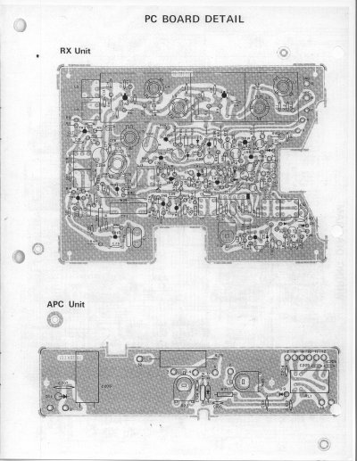
Plan on removing the receiver board to be in a separate box. If you choose to remote both sides, the bud box, CU-347 makes an excellent holder for each unit. Those boxes are a tight fit, so you'll have to modify the boards, a little, by trimming some of the edges down. The local volume and squelch controls are either on the panel or the interface board inside the radio. The latter arrangement discourages "sticky fingers" (unauthorized persons) at the site playing around with the equipment.
Electronic Modifications
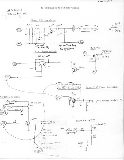
Starting with the transmitter, you need to build an direct frequency modulator, or F.M. This can be performed with basic parts including the actual modulator either from a veractor diode or even a common NPN transistor, such as a 2N2222 or 2N3904 by using only the base to collector junction. The former is the better choice and a little easier to control frequency drifting with temperature changes. If you wish further details on true F.M. conversion click here for more details.
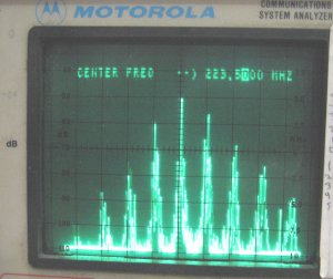
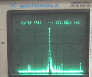
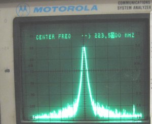
The only other weak area to be aware of is the tendency for the transmitter to send out spurious radiations to exceed limits, so be sure to tune the unit with a spectrum analyzer, if possible. Remember; watt meters are not frequency selective and will indicate power from any frequency within it's range. The left picture shows an aging unit with some corrosion, causing real bad spurs to transmit. The middle picture indicates most of the problem was tuned out and under control. The right picture is a narrow sweep of the middle (better) picture. The "younger" later units that don't have tarnish/corrosion on the chassis and boards don't get quite this bad.
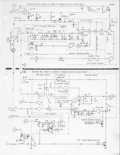
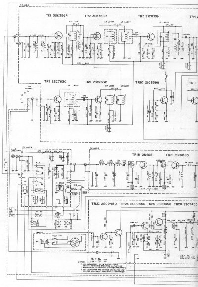
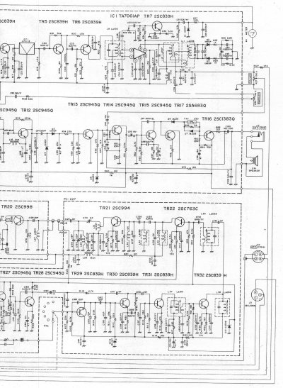
For the receiver the only modification for links are to change out C89 and C91 from the 4.7uf to .68uf. Don't go any lower than that, as will causing the squelch circuit to be unstable. Pick off the collector of TR-13 for the cos point. This is normally an active high. Be sure to use a high impedance device, such as the cos/af board available at this site (plans only). For receive audio pick off the junction of C41 and R26. You still need to equalize this audio, if you want a high performance link, by using the previously mention board.
Here's most of the circuits the author has used since 1977.
Notes:
| Qyt | Description | Value/Notes | Part Number | Cost |
| 1 | Panel | 19" rack,# 2 | Bud # | 14.00 |
| 7 | Machine screw | 10-32, x 1/2" for mounting radio | Fasteners | 0.70 |
| 2 | Machine screw | 10-32, x 3/4" for rear | Fasteners | .20 |
| 9 | Hex nut | 10-32 | Fasteners | .90 |
| 1 | Machine screw | 4-40 x 3/4", phpd | Fasteners | 0.10 |
| 1 | nut | 4-40 | Fasteners | 0.10 |
| 1 | Lug, ring | #10 (for ground) | Radar Elec. | .10 |
| 2 | Standoff | 1"x 4-40x w/Female threads | Speaker mount (A) | .20 |
| 2 | machine screw | 4-40 x 3/4" | Spkr mount A | .20 |
| 2 | machine screw | 4-40 x 1/2" | Spkr mount A | .20 |
| 1 | Terminal strip | 20 position A | Mouser # | 4.00 |
| 4 | machine screw | 8-32 x 1/2" | For TB-1 | .20 |
| 1 | Pin jack | black,for ground. | DigiKey J107-ND | .93 |
| 2 | Pin jack | blue B | DigiKey J339-ND | .93 |
| 2 | Banana jack | blue, B for speaker test | DigiKey J155-ND | 1.05 |
| 1 | Local mic jack | 8- pin, round B | Hosfelt 8PMCS | 2.00 |
| 1 | Local mic jack | 4- pin, round A | Hosfelt 4PMCS | 2.00 |
| 1 | LED, green | For Main pwr indication | 1 1/4 | .15 |
| 1 | LED, yellow | For cos indication | 1 1/4 | .15 |
| 2 | LED, Red, 2 for A | For Tx PTT indication | 1 1/4 | .30 |
| 4 | Resistor | 1K | for LEDs | .20 |
| 1 | Resistor | 4.7 ohm, 2W or higher | Speaker load | .05 |
| 1 | Resistor | 220 ohm | Speaker load | .05 |
| 1 | Resistor | 6.8K | F.M. circuit | .05 |
| 1 | Resistor | 10K | F.M. circuit | .05 |
| 1 | Resistor | 1K (R501) | 1K, 1/4w, 5% | .10 |
| 2 | Capacitor | .22uf (for VHF) | Tx level issue | .25 |
| 1 or 2 | Capacitor | 4.7uf/25v | detected AF line | .25 |
| 1 | Capacitor | 100uf/25v | Tx AF in line | .35 |
| 1 | Bracket | swivel, from 12 ch deck | A | 1.00 |
| 2 | Screw | #6,self tap | A for link bd | .50 |
| 1 | Speaker A | Radius M120 front cover | Hosfelt # | 2.00 |
| 2 | Pot, 25K, LT | 1/8" shaft-A vol and Sq | D-Key CT2228-ND | 3.24 |
| 2 | Knob, round | 1/8" shaft,For vol and Sq A | All KNB-124 | .75 |
| 2 | Pot, 25K, LT | 1/4" shaft,For vol and Sq B | All E. | 2.00 |
| 2 | Knob, round | 1/4" shaft,For vol and Sq B | All KNB-12x | .75 |
| 3 | Switch DPDT, 10amp | For Pwr and spkr control | Mouser 10TC360 | .75 |
| 1 | Switch SPDT, 3amp | For PTT control | Mouser 108-MS 550A | 1.49 |
| 1 | RF connector | Type N-female,M39012 (A) | Chassis, 4 flag | 4.00 |
| 1 | RF connector | BNC-31-120N-RFX,UG447 (A) | Chassis, 4 flag | 3.00 |
| 6" | coax cable | 50 ohm, teflon, for Tx | DUPLEX only | 1.00 |
| 1 | Rx crystal | Ch. ele.-recrystal and comp. | KXN1089B/86A | 36.00 |
| 1 | Tx crystal | Ch. ele.-recrystal and comp. | KXN1088A | 36.00 |
| 1 | cos/af Board | A-Version 5.3-AK2O | FAR Circuits | 06.00 |
| 1 | COR Board | Version 5.4 | COR board | 25.00 |
| . | Parts Cost | As of September,2003 | less ship-Tax | ~$120.00 |
Notes: Color of wires: Black, red, white, green, yellow, orange, blue, brown, violet, pink, slate.
Most of the development and corrections were performed between June and August of 2004.
This may be copied or printed in complete form only for non-profit purposes, such as for the knowledge for the Amateur Radio Service, with AK2O credited as designer. Other arrangements please contact the author.
Copy write: AK2O 2005
![[SRG home Direction]](images/srghome.gif)