![[SRG home Direction]](images/srghome.gif)
Power distribution unit by Karl Shoemaker
Introduction
Many remote (mountain top) sites have amateur stations mostly configured as a repeater. An amateur repeater many have several components, such as the radio (or two of them) controller and/or other link radios, and perhaps some other devices. Each components should be fuse protected. While some of these components have "built-in" fuse protection, some "home-brew" ones may not. A 12 volt regulated power supply (from the AC grid) is needed to power all these items. Most power supplies have one set of output terminals. One (sloppy) way is to use ring lugs for all the equipment, connected to this one point of DC power.
A better way is to distribute the DC power, each with it's own fuse protection. In the case of the PDU (v1) the Author built this on a 1 RU to conserve rack space at the expense of slightly more difficult handing of the lines in close space proximity. In addition a blown fuse indication for each DC was incorporated. While it's not common, an indication can help the technician arriving at the site with a good start on the problem. Of course, the root cause of such blown fuse still needs to be located. A Cinch series 141 terminal block was chosen for a balance of space and current rating for each circuit. They use phillups head screws which is a gross improvement over the old-style straight blade type.
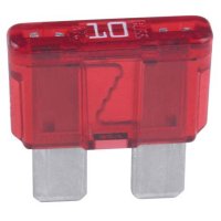
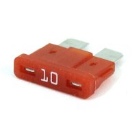
ATC (or O) holder type is used. The "C" or "O" is quite possibly from the different brand such as Bussman and Littlefuse, respectively. It's believed to be superior to the older 3AGC glass type, especially for higher current circuits. This is type has a better surface contact between the fuse and power points, due to the pressure on the point's receptacle. Plus, the advantage of no glass breakage in the event of dropping one on the floor. This type is widely used in domestic automobile equipment. Shown here are the 10-amp rating.
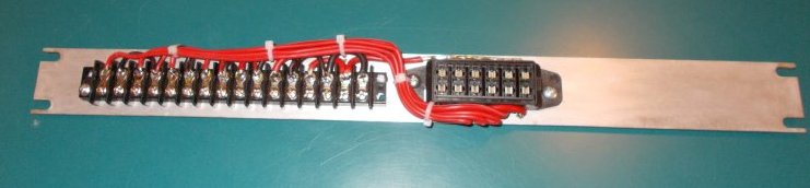
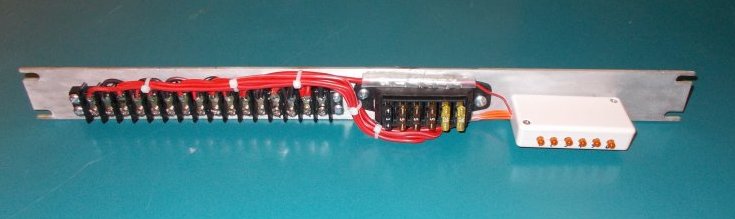
Shown here is version-1 with a six-circuit distribution. This should accommodate all the equipment at most sites, at least for SRG. An eight-circuit version is designed on "paper" but has not yet been built. Another option is two of the six-circuit PDU's connected from the same power supply. If you observe carefully, there appears to be an extra "pair" of terminals near the right. To ensure good current rating from the total station load the last two pairs on the right are parallelled, and with heaver gauge wires. This point is the input (from the supply's output). The rest of the terminals to the left distribute the 12v DC power to the equipment. It's designed for a negative ground system therefore, the minus lines only have short jumpers for the distribution. They are mostly not visible behind the positive (red) wires. At this point the fuses and indicators have not yet been installed.
Shown here is the indicator section installed.
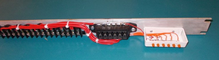
Show here is the completed unit including some fuse values. The final values will be selected during the install at the site. Looking carefully across the "top" of the fuse holder input is a piece of shrink glued in place for short-circuit protection at the site. The Author used a (crude) marker to number each circuit. A more refined way might be to use a tape label.
Here's the
schematic drawing for the unit.