Introduction
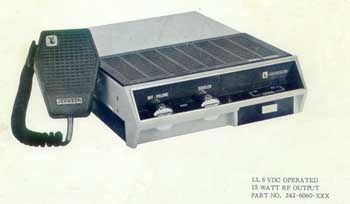
The E.F. Johnson PPL6060 UHF radio makes a good link radio. The Transmitter is direct F.M. and the receiver is pretty flat, without modification. This particular radio has poor sensitivity in the Amateur band, however, for a short link application (path) it's not worth changing out components to get the receiver back to specification. The transmitter tunes up fine in the Amateur band, with an output of +38 dbm*. After long key down the rear heat sinks enough for the single final transistor. Being a mobile, however, it only has 5ppm spec for stability. One can improve this to a base station spec (2 ppm) with a few component changes. This document will go over the modifications and circuit additions needed to make the radio into a good link.
Acronyms, Definitions, Radio System Operation and Theory:
Amateur Radio is to develop the art of radio and improving operating practices. This can set a good example for others, including the commercial industry, to what Amateur Radio system(s) are capable of doing to provide public service communications in time of need. This includes the technical side, to produce good operating repeater systems. We will start with very basic theory.
Two-way radio systems send intelligence (voice, data, etc.) by modulating the originating transmitter and decoding (detecting) this modulation at the far end receiver back to something usable to be understood. How well this is understood depends greatly on how well the system is set up. Anyone can build up a system work, "throw" it together and it will work, somewhat. This discussion promotes a better way. For one, Technician organization and discipline is necessary. Plan on what you want to do for a system design and stick to it. Think and justify any deviations from your "rules". Force yourself to keep good practices. One method to keep the guesswork out of working on a system is to establish level references. Some call these "benchmarks", or "baselines".
Most 2-way systems use the audio (AF/VF) portion to modulate them. A typical (commercial) system uses 300Hz~3KHz for modulation and detection for a voice "channel". For this discussion, frequency modulation and level is somewhat different. While old Amateur methods used linear (volts, watts, etc) units of measure, most figures here mentioned are in logarithmic units. Once accustomed, it's easier to see the entire picture this way, when designing a system, checking frequency response, or even doing path analysis and keeps the guesswork out of trouble shooting a subtle level problem.
References can be expressed in a few acronyms. Test Tone level (TTL) into a two-way VHF/UHF transmitter or out of a VHF/UHF receiver is referenced to a test tone frequency of 1 KHz, of %100 system modulation. For this standard, that is +,- 5 KHz deviation. Other areas and services have different bandwidths, such as in P-25 systems. A Test Level Point, (TLP) refers to a measurement point, on equipment, for a system, in reference to Test Tone Level (TTL). TLP provides easy reference to any parts of the system for measurement and alignment. 0 dbm is referenced to 1 milliwatt at 600 ohm impedance. Therefore, a transmitter AF input with a TLP of 0 dbm, with a Test Tone Level of 0 dbm tone input, would fully modulate the system. A far end receiver with the same TLP would output a 0 dbm tone as well. A 6 db drop in (voltage) level would reduce the modulation in half, and so on. In general, for these standards, levels are stated in transmit-receive (Tx-Rx) order. Therefore, an audio (VF) "drop" TLP of 0/0 would mean a Tx TLP of 0dbm, Rx TLP of 0dbm. Sometimes operating levels are not at TLP. To avoid technician confusion two sets of numbers are sometimes used in diagrams and on the physical equipment. Figures in parenthesis are the TLPs. Non-parenthesis figures are operating levels, and, as mentioned, may be at a different levels from the TLPs.
Long haul RF links are made of several transmitted and received signals. Each time this occurs some reduction in signal quality happens. Stock two-way radios are designed for single path operation, with it's own pre-emphasis, deviation limiting (clipping) and receiver de-emphasis, and "forgiving" squelch operation. For multiple links, these stock radios can add gross problems, such as excessive distortion, audio frequency response being very poor and very long squelch bursts. All these conditions will cause a system to operate badly and be rather annoying and fatiguing to listen to. These conditions can be corrected, and is done so in all SRG systems.
For the transmitter condition, the mic input is not used, rather, the direct F.M. section is either used or built. This directly modulates the transmitter to provide flat response.
Each time you limit deviation for each hop will add more distortion. To correct this condition, only limit the modulation at one point, such as the system's controller. This is why the links should not be limited, rather passively 1:1. If you do have to limit, one option would be to set the system limit at 6 KHz and let the system user's transmitters limit at 5 KHz deviation. Passive mode requires system management and user responsibility. This may require some enforcement on the user's part. (There are other circuits to "punish" over modulated users which is beyond the scope of this documentation.)
For the receiver's audio frequency response condition, take the audio off the discriminator. All receiver's discriminators should have great low end response, however, (due to IF filtering restraints) the top end always rolls off too soon. The (before mentioned) audio boards have circuitry to equalize the higher end to extend the response.
For the long squelch burst condition, some theory is needed to be discussed. FM receivers have large IF gain. At the discriminator there is plenty of noise available during signal absence. This noise can be filtered to the top end (i.e.,8-10 KHz), amplified, rectified and DC amplified to usable DC levels. This is known as a noise operated squelch, used on every 2-way radio, and "scanner" today. A signal into the receiver will "quite" the discriminator audio output, which changes the DC levels in the squelch circuit and turns on the audio amplifier to drive the local speaker for listening. It also can be used to operate a link board, and finally, to key an associated transmitter, thus making a repeater. More commonly known as "COS", or Carrier Operated Squelch. Some use the term "COR" (Carrier Operated Relay) which came from the old tube radio days. Both are the same function.
Stock radio receivers have squelch constants (time for squelch to close and mute the audio path) designed for both fixed (base station) and mobile (moving station) signals, therefore, a fairly long(200 msec.) time for squelch close. This is noticed by a burst of laud noise at the end of a received transmission. For a single site this is tolerable, however, for multiple links (hops) this can quickly add up to something annoying to listen to. It also slows down switching paths, causing user frustration. For links this problem can be easily corrected by lowering the R/C constants in the squelch circuits. To shorten the squelch burst the capacitors in several areas of the squelch rectifier area can be reduced. This requires some careful selection. If they are too low the circuits will be unstable. Links are not intended to receive mobile (moving) signals. Therefore, this modification will be transparent to fixed (links) station use, which should be full quieting, strong signals. Only multiple "clicks" would be heard with this modification. The remote user receivers will still have "stock" squelch constants, therefore, will provide for moving (mobile) signal changes, plus "cover up" the multiple link "clicks". The result will sound like a simple, small, single site system. The values are discussed later.
Mechanical Modifications
The radio is rack mounted with the controls on the front panel. Since the local mic jack is rear mounted, and the mic is 'hot' all the time it's normally left un-plugged. It's handy to have all the controls right in front, which include power, local speaker, volume, squelch, and CTCSS (Rx tone) control. There is a COR-AF board inside the radio. This board takes in the unsquelched (flat) detected audio, is squelched, and equalized, if needed, then amplified to a usable level for a link port. A metal strip holds the COR/AF board inside the radio. An 8-Pin jack is rear mounted for the link functions.Electronic Modifications
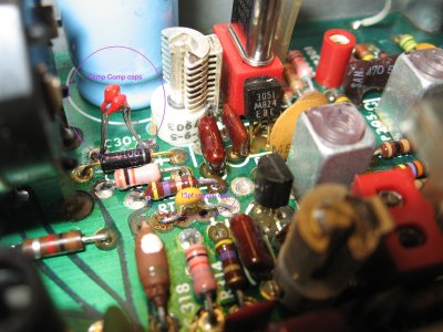
Starting with the transmitter, removed C311 and RT301. Replace them with a single 15pf normal coefficient capacitor. Use the outer holes to make the connection. A good part is Mouser Electronics 80-C315C150J1G. Next, remove C309 and replace it with two 15 pf capacitors with a negative temperature coefficient of 3300, thus the designation on the cap "N3300". A good part number is Motorola (industrial number) of 21-82358G98 (may be "NLA", however). Power up the radio and netting adjustment should now be possible with the trimmer, C307.
You can check the temperature range to verify proper operation, like the Author did. Place the radio in the refrigerator at 42° F for about one hour. Then check the frequency. It may drift about 300 Hz high, which is acceptable. Typically it's much less. Next, place the radio in an oven with the low setting of 120°F for 15 minutes or longer. Be careful to monitor the environment with a thermometer to avoid overheating the radio. Most ovens won't go this low, so you'll have to cycle the controls manually. Then check the frequency. It may drift about 300 Hz low, which is acceptable.
To extend the low end response, change C303 from .047 to .27 uf. You can drive the top of the DEV pot for flat Tx AF. However, this will load down the local mic's audio. The use the internal modulation amps, and make them flat, remove C324, C325, C326 and R333. Install a 100K resistor where C326 was. This is essential for the negative feed-back loop of op amp U301D, and is a handy way to control the gain of that stage. This value gives the Tx TLP range about -5 dbm, by using the DEV pot, R305 to fine set the TLP (for +-5 KHz dev for a -5 dbm tone input). Change R328 from 150K to 22K. This will balance the sensitivity between the local mic and Tx AF input.
For the receiver, the CTCSS (tone) board functions: It uses a "closed loop" for tone control. This means the loop from ground to the HUB needs to be closed for tone mode operation; open for carrier squelch (monitor mode). (same as Motorola) To disable the tone decoder from muting the receiver, remove R269. To disable the tone encoder from sending Tx tone, cut the run near the plug pin 6. Change C110 value to extend tone encoder frequency range.
Remove the Hang Up Box (HUB) wire going from C.G. pin 1 to mic pin 4. Install a SPST switch on the front panel with one going to ground and the other to the C.G. board pin 1. This is the HUB function. When the switch is on, the receiver is in tone mode (tone "and" squelch).
For cor "AND" squelch install a 10K resistor from U202-10 to the hole that goes to the C.G. board, pin 2. Pin 2 side now is the cor output that goes the COR/AF board. If the Receiver is in tone mode the cor circuit will only go active with carrier and proper tone received. You still can open the local speaker's squelch for monitoring without activating the cor.
The radio doesn't have the Micor silent squelch. However, you can greatly shorten the squelch burst, when a user unkeys. There are capacitors for time constant/squelch changes.
To shorten the squelch burst:
The following is a summery of the radio hookup and functions:
| Radio Function: | Mic Pins: | Rear 8-Pin Jack | Remarks: |
| Mic hi | 1 | . | . |
| Tx PTT | 2 | . | . |
| Ground | 3 | 5 | . |
| nc | 4 | . | . |
| Tx AF in | . | 1 | TLP 0 |
| Tx PTT in | . | 2 | Active low |
| Rx AF out | . | 3 | TLP 0 |
| Rx PTT out | . | 4 | Active low |
| Mode | . | 6 | Future CTCSS control |
| nc | . | 7 | . |
| nc | . | 8 | . |
Notes:
* +38 dbm = about 18 watts for "old school" LMR people.
This may be copied or printed in complete form only for non-profit purposes, such as for the knowledge for the Amateur Radio Service, with AK2O credited as designer. Other arrangements please contact the author.
Copy write: AK2O 2012
Back to: http://www.ak2o.org/srg/tech.html
![[SRG home Direction]](images/srghome.gif)