













Introduction
Amateur communications can use point to point in a simplex RF path. Some have some limitations depending on the frequency band(s) used. For lower HF is dependent mostly on ground waves while middle HF is dependent on the F2 layer (skip path) in the upper atmosphere. VHF and UHF is dependent on a line-of-sight path. Simplex communications is on one frequency. Because these last two bands are line of sight the signals are blocked by obstacles such as buildings and hills. Mobile and portable (hand-held) increases this limitation. A station in a high location can get around most of this limitation. However it's impractical to be a this high location, not moving for a long time especially under winter conditions. Therefore, a remotely operation station in the form of a "repeater" is the solution and a great improvement for RF coverage over low-level simplex work.
Antennas
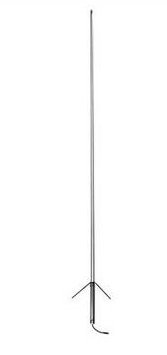
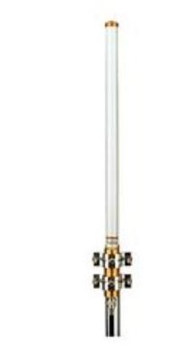
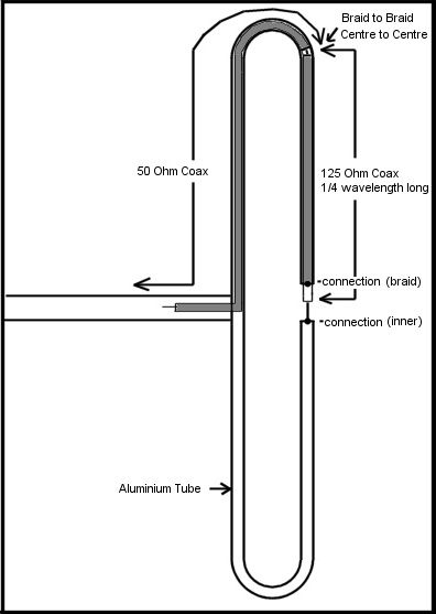
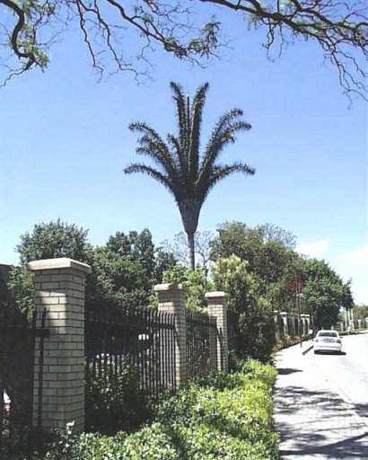
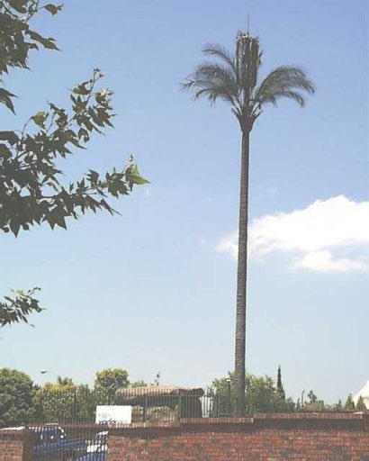
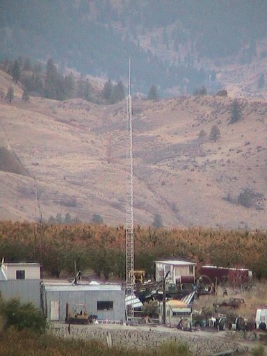
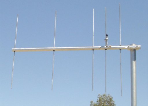
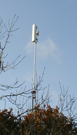
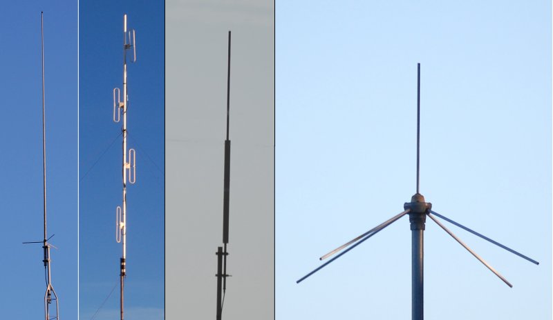
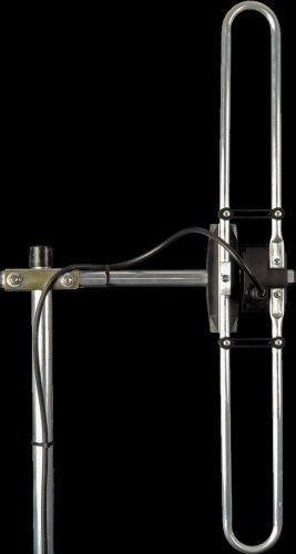
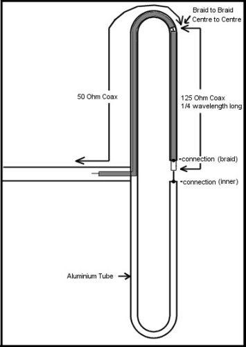
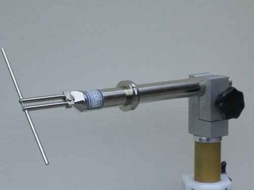
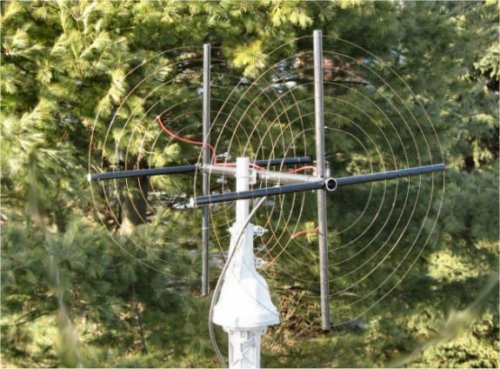
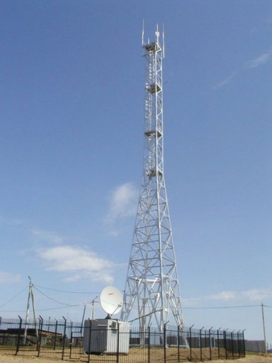
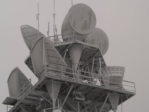
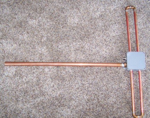
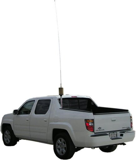
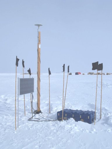
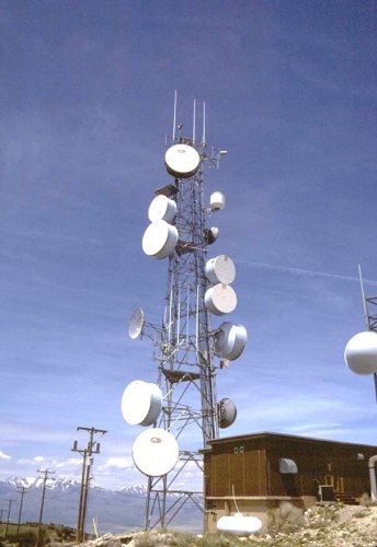
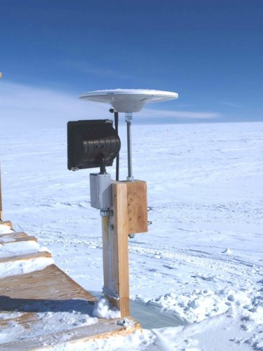
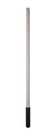
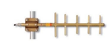
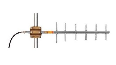
Antennas come in many type shapes and forms with various gain functions in omni or directional. Some are disguised to look like a tree or large rock.


A Repeater normally operates on two frequencies; the users signal goes in on one, while the repeater retransmit's the user's signal on another. The other users enjoy increase coverage and is especially valuable during a conversation among several users, whether operation in base, mobile or portable methods. This repeater normally receives and transmits at the same site (location). In order to do this there has to be RF isolation between it's receiver and transmitter frequencies.
Some repeaters operate a separate antenna (and feed line) for each receiver and transmitter. However, the cost and labor is high because of these two components. Most repeaters operate on a single antenna (and feed line) for the advantage of lower cost but with other considerations. The isolation requirements are high as compared to using separate antennas for the repeater.
There's two areas of concern to operate a good repeater station:
Managing a repeater or other type of station at a "busy" populated communications site:
The station's receiver sensitivity is very important to provide a user's (subscriber in the commercial world) signal to be usable for re-transmission to the other user's reception. Receiver sensitivity (performance) can be reduced from several sources. A common one is desensitization from other nearby stations. Another is spurious and mixing of RF signals from your's and other stations in the area. Filtering for both situations will be discussed here.
Most repeaters and base stations in the Land Mobile Radio (LMR) industry use FM mode transmitters. These transmitters have "final" RF amplifier (PA) stages which many times run in class-C. That means these semi-conductor devices (transistors, for example) are non-linear. If RF levels of both the intended transmitter and another outside are strong enough they will "mix" in the PA to produce more, unwanted RF signals. This situation is refereed to as inter modulation distortion, or commonly called "IM" or the slang "inter-mod" by technicians in the industry. This is true for any LMR system, commercial, broadcast, government or amateur. We will focus on the latter.
Here's a case for an unwanted mix of 2 signals. We will cover only the third order mix, since this is the most common and highest level type. You have a transmitter on 147.00 MHz (frequency "A") and your "neighbor" has a transmitter on 146.00 MHz (frequency "B"). You double the frequency of A; being 294.00 MHz, minus B; second which comes out on 148.00 MHz being an AB mix. More accurately, A2-B mix. Or, you can reverse the two transmitter frequencies therefore, 146.00 MHz double is 292.00 MHz minus the other comes out on 145.00 MHz, B2-A mix. The Author calls this basic IM situation as "ABBA". The ia a mathematical relationship involving the frequency A and frequency B in two combinations.
At first you make think this is no problem since it does not get into any repeater inputs. ----- Wrong. ----
You and your neighbor are generating an unauthorized signals and creating a possible interference situation especially, if this mix is strong.
Also, you and your neighbor's IM products can be "heard" by a third nearby transmitter to create even more IM products.
If this gets out of hand can really mess up a communications site.
RF mixing can occur in transmitters whether they are energized (RF output carrier) or not. That's because most RF amplifiers while not energized (with intentional RF) still have DC supply power going to the devices. Class-C devices normally do not draw significant power while not energized with RF. Again, to stress this "intentional" RF, being your transmitter's operating frequency. Signals are designed to go out of a transmitter's RF port to its antenna or associated equipment, such as a duplexer, then to the antenna. Other signals can also go in the reverse direction from the antenna, down the feed line, into a transmitter to cause the mix; thus, IM.
When identifying such a mix one clue is one of the signals while there is modulation going on will be distorted and laud. That's because the second harmonic also doubles the deviation of an FM signal and most likely the receiver you are hearing this result won't handle twice the amount of modulation of such signal. In some complex cases you may observe several of these types.
Proper RF management is very much needed in cases like this. There are "fixes" or what the LMR industry calls "solutions" (to these problems). As discussed in another article, a band-pass cavity filter is your basic prevention of unwanted signals going into your transmitter. However, it does not stop there. In case where a close-by frequency is there, your single cavity won't filter that out. In this case you will need an "isolator". This device is like an RF one-way valve, allowing intentional RF energy to leave your transmitter (to the antenna) but block the reverse RF back into your transmitter. Both filters and isolators are rated in log on the RF levels they management. This is a measure of their performance; related to the cost to purchase. Also, there are practices to properly tune and operate these devices. For example, operating only with an isolator can do more harm than good. That is because isolators in themselves are non-linear devices. Last word about a band-pass cavity is it needs to filter out the second harmonic (minimum) to do any good for RFI protection. In some installations use several combinations of these and other devices. For example, a repeater usually will need a duplexer, to transmit and receiver on the same antenna. If the duplexer has pass characteristics, that is best, but in addition, a single low-pass filter will usually take care of the second harmonic, plus the isolator to keep the RF going in the forward direction only. The normal connection is the isolator is on the output of the transmitter, followed by the LP filter, followed by the duplexer, then line and antenna outside.
There are a few exceptions to this advice; for example, if you are the only station at the site with no nearby stations to electrically interact with yours may be acceptable. This is also in the case of a "ham" operating at home or in the mobile. As mentioned earlier, it's a different situation at a remote mountain site, populated with other stations. Some major site owners/managers have "site requirements". Among proper grounding shielding, etc., they will specify filter performance requirements. These guides are a minimum and can be exceeded if you have a special situation.
There are also other situations such as, the site owner is not concerned about protection therefore, you are on your own. But this could have negative affects in the future. Just remember in the future; if there is an RFI problem in the area and you are found to be the cause you will have to be the first to take action to correct it and possibly the first to blame in any future problems. It's expensive for an affected customer to pay for a commercial radio shop to find the root cause of interference which could lead up to several hundred dollars. To make matters worse this effort by the shop won't be noticed until it's too late to save your reputation. In some cases the offended station and person will be upset and maybe even hostile; discovering you did nothing for site (filtering) protection. Therefore, as a pro-active plan, a pass cavity is the bare minimum one can install on a transmitter at a populated remote site.
Another note is most "ham" amateur transceivers have a single RF port for receive and transmit. Therefore, an isolator would not properly function. That's because it would block (as its suppose to) to any received signal coming down from the antenna. That's why its generally a bad practice operating a mobile (or HT) transceiver at a populated site for example, for packet or APRS operation. Commercial equipment is designed for sites by building out the receiver and transmitter and its ports. In the case of a (simplex) remote base station an external TR relay, or other device is used thus, permitting installation of an isolator. The last point is most "ham" receivers do not have the front-end selectivity needed to operate at a populated site like commercial equipment can. Using properly set up commercial equipment can avoid wasted time, frustration and problems with your "neighbors" at these types of sites. Using commercial equipment can also set a good example to other hams and site owners as well, to show they can do a good job operating a station.
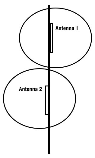
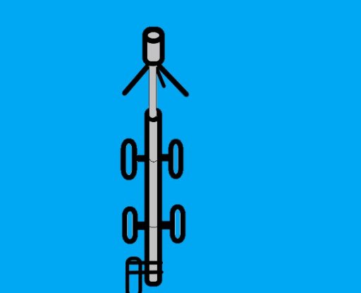
Another problematic senereo is a "new" station is added without advising or testing with the other tenants, possibly hoping the others won't know about this unless a problem is discovered. One example for the sub-band repeater pairs operate in the 144-145 MHz are. In the event this "new" station is an APRS possibly operating (simplex) on 144.390 MHz is too close to the repeater mentioned. In some case the difference between the APRS and repeater input is 400-600 KHz apart. Without the proper (and expensive) filter the APRS will desense the repeater's (input) receiver making it "deaf". Also, if horizontal spacing of antennas is practiced will exasperate the problem. A trained and skill RF engineer or technician will know vehicle spacing is several times more effective if the lower antenna is in the cone of silence of the upper one.
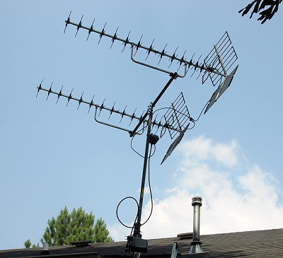
Shown here is a poorly engineered cluster (pun intended) set of antennas on a very expensive mount, possibly on a sea vessel. The next one is just a set of two, but way too close to each other as well. This reflects lack of training, experience, ignorance or just plain carelessness. The middle and right ones show examples of improving antenna isolation because lower one is in the cone of silence of the upper. Around 30 db isolation can be realized especially, if the distance is a few wave lengths from each other.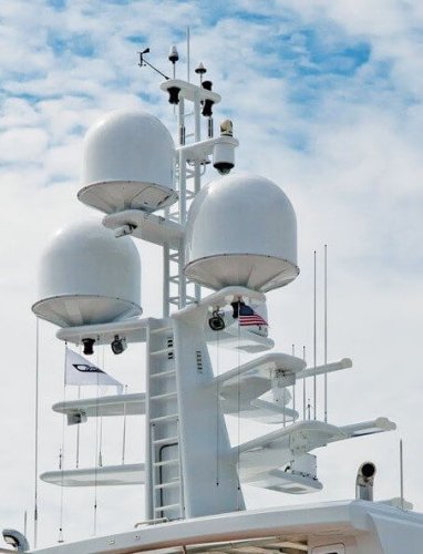

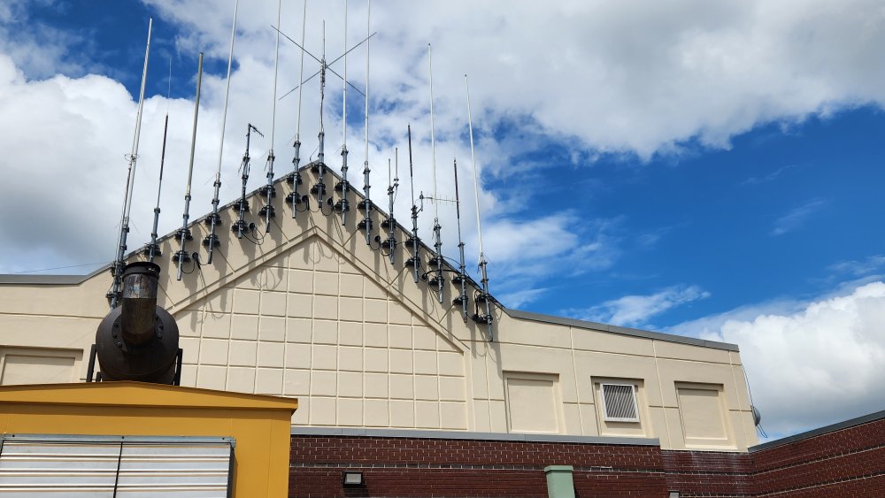
This image is an example of an organization does a fantastic install of many antennas however, is clueless about the electronic side of operation. Assuming (in all fairness) if the equipment has no filtering and/or isolators installed (in the correct configuration) this can be a rich-medium for PIM and AIM the whole area to experience, to say nothing about a remote radio site. Typically, management directs the "techi" people on appearance and does want to hear about electronic performance until it "bites them in the butt".
The other contributor of bad antenna installation is no understanding of logarithmic principles for which antenna's gain is rated that way. Most "hams" think of power in the "watts" scale and have little or no interest in the real world using the other scale and understanding. For example, the "new" station thinks "I'm only running 3 watts, so there should not be any problem". - - - Wrong - - This type of ignorance will lead to RF interference problems.
There are other sources of IM (mixing). For example, is "PIM" being "Passive IM". PIM is common with defective antenna connections in the transmission line and its connectors or even a defective antenna outside. One classic case was a major manufacture of collinear antennas, using two or three dissimilar metals, such as aluminum brass and copper. In time, galvanic corrosion will produce a substance which is a prime result to function as a semi-conductor hence, a PIM source. Other sources could be loose hardware on the tower or even a chain-link fence. Pretty much any metal to metal contact that has some rust or other type of corrosion is a candidate for a PIM source.
One of the Author's colleges has written a very nice article on isolation protection which the Author highly recommends reading.
The Author worked at a test and measurement lab for 2 years to heighten the PIM awareness for himself and to help others be aware as well for amateur radio projects. It's too bad this Company did not make PIM measuring equipment for the amateur bands, especially for the 2-meter, 1.25 meter and 70-cm amateur bands. This equipment is mainly geared toward the cellular industry where the real money is. The Company is Kaelus which produce quality test equipment therefore, would like to share this one document from them.
For a basic understanding of how a repeater (station) works can be viewed here . This presentation was originally designed for a seminar in front of a group viewing an overhead screen. Therefore, the font may appear very large on your PC's screen.
Toning (CTCSS for example) a receiver only blocks (ignores) RFI from PIM or other unwanted signals. Therefore, one would not be aware this is a problem going on since it's not heard. In some cases it's actually better to be on carrier squelch so any RFI is obvious to the technician listening to the affected equipment. The wikipedia has a nice article about toning and interference with uses (subscriber) here.
![[SRG home Direction]](images/srghome.gif)