.jpg)
Introduction
The Author has been making commercial antennas for years. This is a report for a another commercially made one.
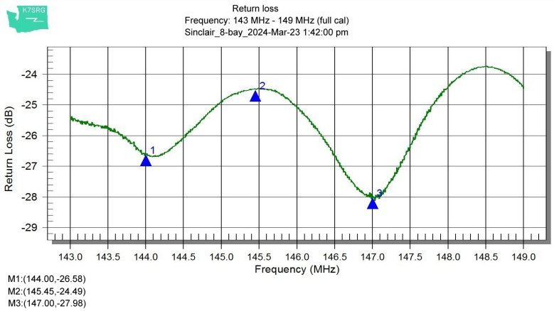
This one is built for a heavy duty application for an amateur station on a remote high site with ice loading. It consist of eight open loops with a coaxial harness, mounted on a heavy duty aluminum pipe. It has good return loss. The feed point is terminated with a type N male connector and is in the middle of this pipe. This area makes it very difficult to connect to the feed line going down the tower to the equipment room. A jumper installed to extend this point to the bottom appears the only solution.
.jpg)

The even though there is no instruction manual available this spec sheet can help.
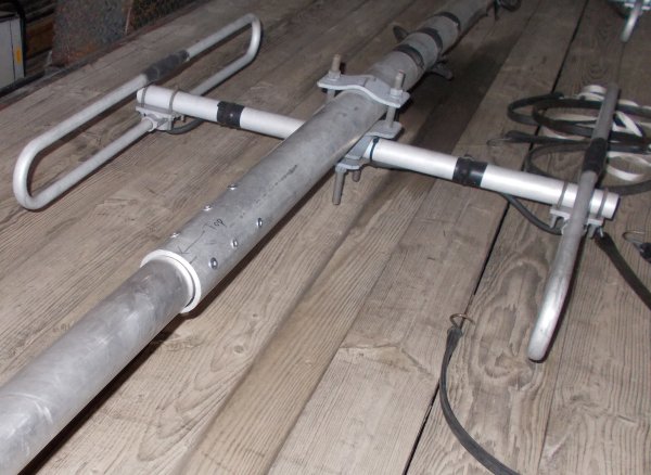
This antenna is to be mounted on a tower with horizontal pipes for top and bottom mounting about 23 feet apart. Since the antenna is a little short of this span an extender pipe was added and secured with 1/4" blind pop rivets.

When ordering rivets for a project like this, it's important to use the same type of metal as the pipe, in this case, aluminum. Joining dissimilar metals could promote PIM especially if one or both has corrosion on the surfaces that touch. They are identified with an industrial number:
The first part of this number is the diameter of the rivet (and it's hole into the material) in increments of 32nd of an inch.
The second number is the length of the "stem" pull ranges in increments of 16th of an inch.
For example, a "88" (sometimes labeled as "8-08" or "8-8") is 1/4" by .625"-ish. Being that 8/32= 1/4" and 8/16= 1/2".
To further illustrate this formula here's a chart.
Note: if you look closely the "-x" numbers should be on the right of the description; such like "x-" being a column is showing the diameter as just explained
.jpg)
This may be copied in complete form only for non-profit purposes, such as for the knowledge for the Amateur Radio Service, with the Author credited as designer. For other arrangements please contact the Author.
![[SRG home Direction]](images/srghome.gif)