![[SRG home Direction]](images/srghome.gif)
Introduction
The Author prefers some features of this radio such as the green display and dual external speaker output jacks. The radio appears to work fine within the specifications published. Only one minor flaw was found and corrected. The hand mic PTT lever being plastic rubs on the housing causing a squeaking noise over the air. One drop of machine oil corrected the condition. A swap tip or two was used to spread the oil in the area and clean of any excess. Simple removal of the mic shell is required for a complete repair. To note: the latter radios have a different hand mic with the OEM box. This perhaps was from this minor issue.
For the V71A the microphone is better (larger) than the Yeasu FT-8900R (which the Author owned), plus the buttons are a little larger, making easier operation. The "soft" button assignment for both the mic and front panel have sufficient selections however, some tasks are a little awkward over the 8900R. One little quirk is pressing the up or down on the mic button changes memory slots, but does not start the scanning (like the 8900R does-nice feature). The receive audio is satisfactory. The transmit audio is also satisfactory, which was a relief; the transmit audio on most Yaesus have all been very good (good pre-emp, etc.) where some of the other brands are tinny. The Icom IC-230 was a classic example. It will not "handle" high hash for the DC source therefore, you need to perform a good installation with the DC power leads going directly to the vehicle's battery.
Speaking of the microphone the older radios had the MC-59. That's believed to be the one with the (nice) lever type PTT. The newer radios are supplied with the MC-62W, which has a rubberized button on the side for the PTT. The Author found the latter annoying therefore replaced the second radio purchase with the older type. Having said this it's found most hams prefer the newer type.
The Chirp (free) software was found to be inadequate so the Author purchased the good software from RT systems. The radio handles high RF environments (like the 8900R did). The other "feature" (not a flaw) was the back of the mic had steel "bubbles" to make it fit tight in the holder on the dash board. It took an effort to pull the mic off the hanger to use it. By removing those bubbles and now it sits and removes real easy from the hanger.
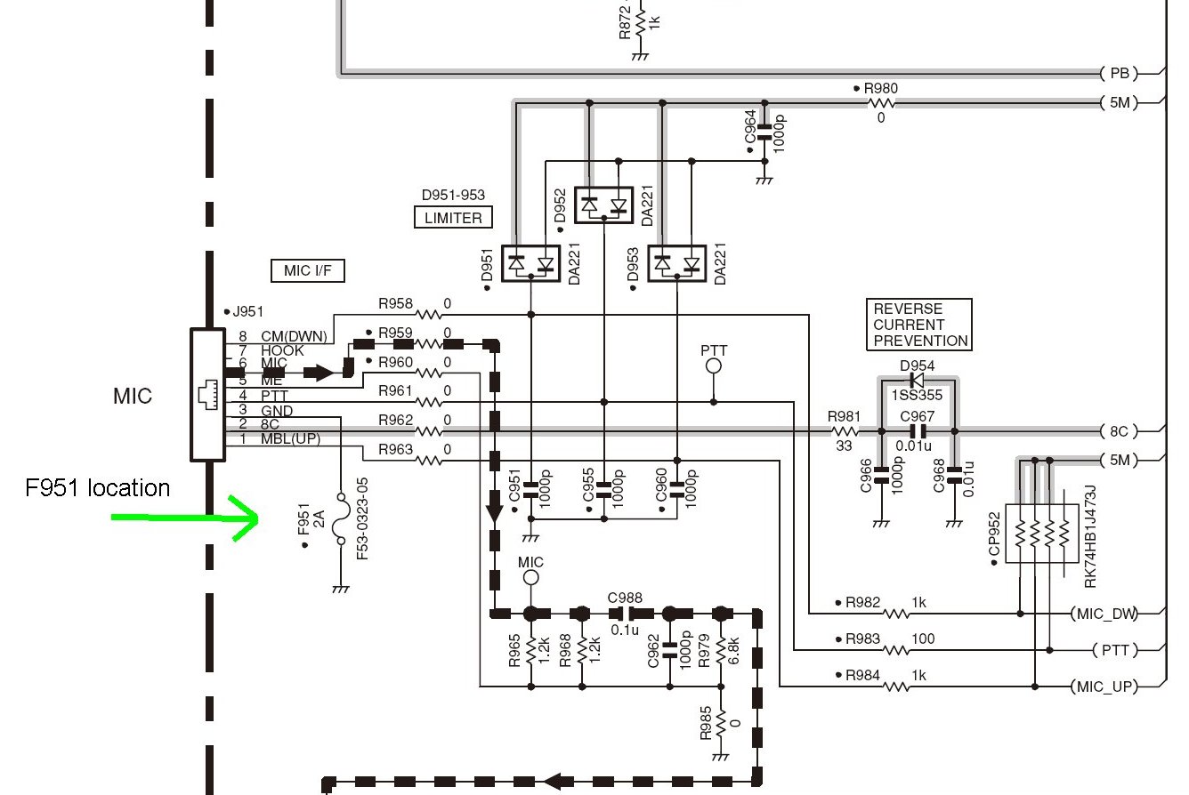
There is a potential issue with the location of one of the fuses which supports the ground return to the hand mic. It's hard to believe the fuse would blow, being a 2-amp rating. In the event, you can either send the radio in a qualified center or do it yourself. If you choose the latter, you need to have skills with SMDs. The Author does therefore, would like to share this information. It's " F951 " which is a tiny "chip" fuse. It does require removing the main control board by removing several mounting screws and the solder connection for the RF connector in the rear. Here's the details on the location of this little item. The images are left huge, so you can easily see the little item on the PCB.
.jpg)
.jpg)
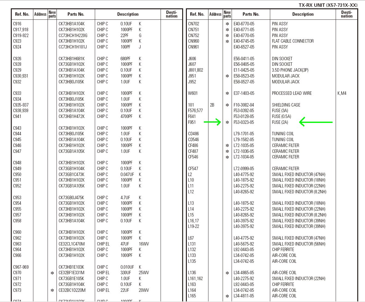
In the event you wish a "real" RF connector on the radio you can change the UHF to a type N. The part number for the type N connector is found with the green arrow.
 PNs.jpg)
Most amateur radio transceivers have an unrealistic "S" meter. Most signals show way too high of a received signal level (RSL) especially in the VHF-UHF radios. You can calibrate the meter which requires some adjustment. Once this is done one can plot an AGC curve for a log scale for better system evaluation and reports to fellow amateurs.
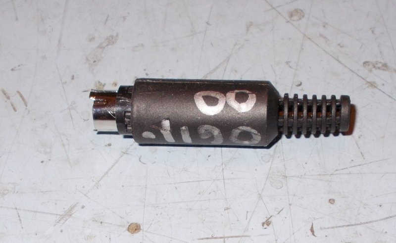
In the event you wish to alignment this radio there's a procedure to get into this "techi" mode. First, you need to purchase a "jig" available from the OEM. Or you can choose to build your own, as the Author did. This is a simple mini-DIN plug (6-pin) that plugs into the back of the radio's "data" port.
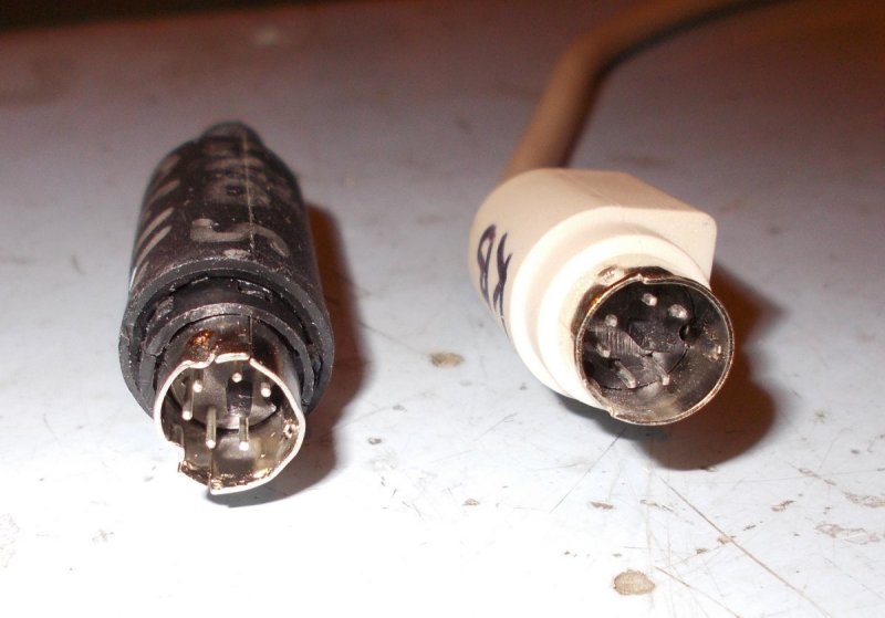
The original plug was made up with a mini DIN plug only. The jumper between pins 3 and 6 are inside the housing.
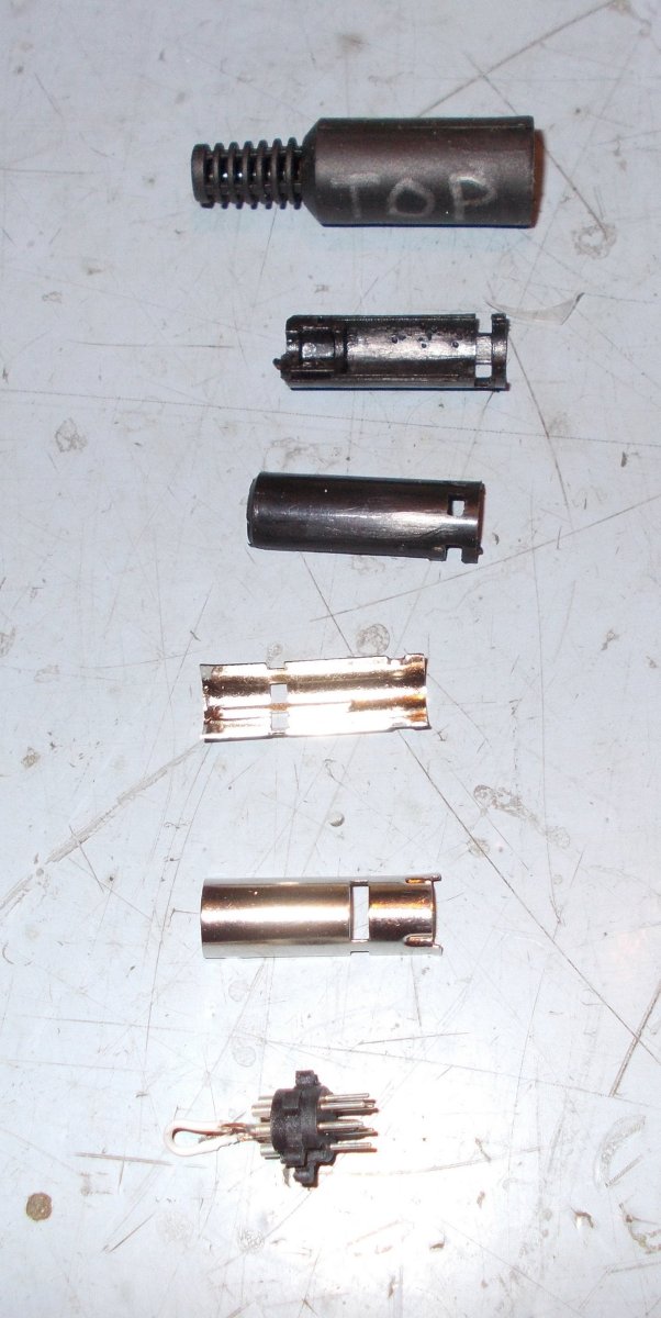
Here's the plug taken apart. There's a disadvantage to the fact the outside section sometimes slides so the plug is not fully inserted and does not make contact. This became aware to the Author after troubleshooting a problem of the radio not going into the adjustment mode.
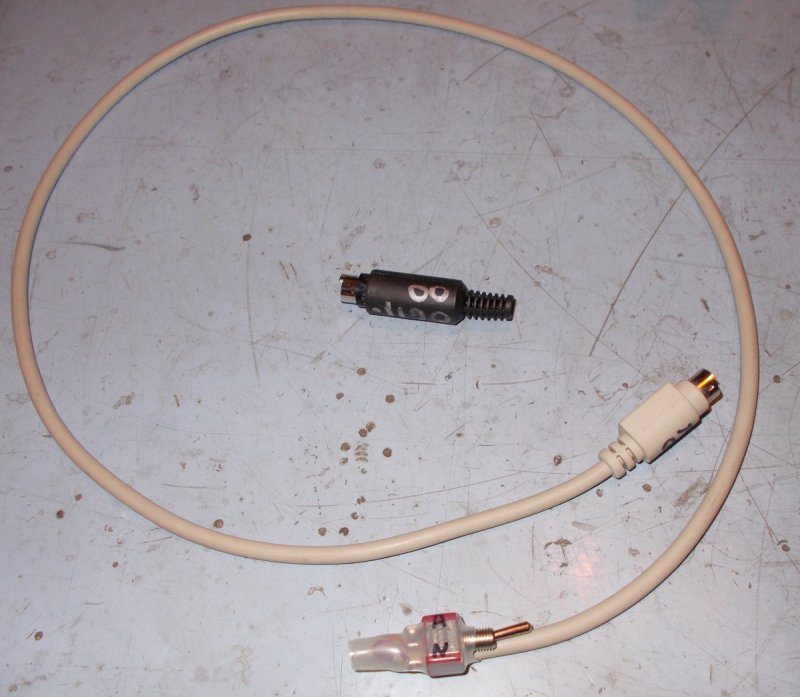
Therefore, a search for a better system was done. One thought was to take apart either a keyboard or mouse but not all the pins are connected to the cable's wires. However, a common PS-2 extension cable was found that had all 6 pins connected (plug a drain wire). Since only the two wires were need for this project the others were cut off. Shown below is the cable type on the right. Note: another area of needing checking is the little (plastic) tab near the center of this plug. Some are "fat" where-as it may damage the receptacle in your radio. The Author found a small size one that worked great.
Shown here is the complete (ver 2) jig. A couple layers of heat shrink over the cable end and switch keeps it managed. Project took less than a hour on the bench.
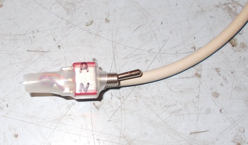
Here's a close-up of the second version. Using a switch allows one to leave the plug inserted while going back and forth between alignment and normal operation; hence, the A and N labels. This is convenient because you cannot leave the plug active while running in normal mode. If you do this the radio will error.
For the adjustments (alignments);
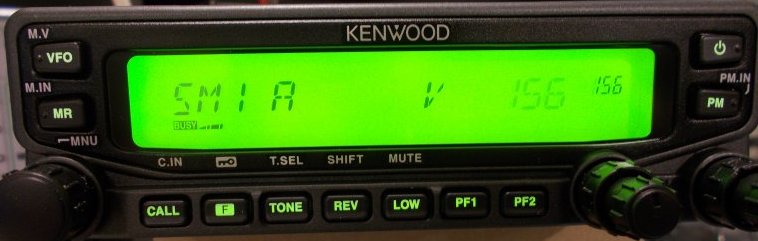
Here's an example in adjustment of the signal strength meter for an "S-1" with a specific RF level into radio. In this case is on 2-meter band, A side of the radio. The one from the right is the ("hex") figure from the RF level into the radio. Press the knob to write this figure into the memory. The far right number now will be the same as the other one.
Back to the first mode, rotate the knob to get to the SM or other functions. The functions that will be worked on is, SM, PWR, DEV and CT. Press the knob to get to band selection.
There's a fairly nice site for replacement parts:
If that (direct) link is broken go to their
main site and search for the radio's model number.
This article may be copied in complete form only for non-profit purposes, such as for the knowledge for the Amateur Radio Service, with the Author credited as designer. For other arrangements please contact the Author.