Introduction
Packet radio consists of stations talking to each other in the AX-25 protocol, mostly on 2-meters.
| Area you wish to contact | Node | bps |
| Spokane | WR7VHF-4 | 2400 |
| Chewelah | K7SRG-8 | 2400 |
| South of Spokane | WR7VHF-3 | 2400 |
| Basen | N7HHU-? | 2400 |
| Upper Columbia basin | N7EBB-? | 2400 |
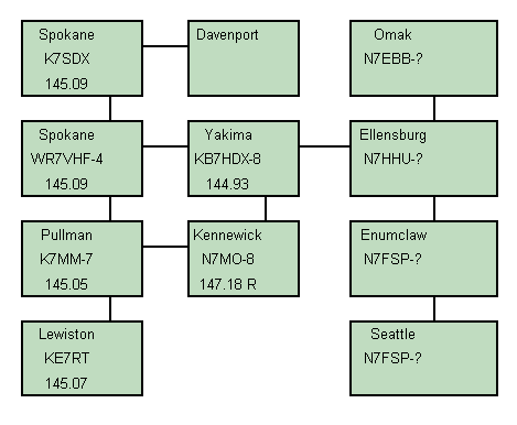
Even though packet radio, using AX-25 protocol presently is not part of SRG, we support that mode. If anything else to identify interference, should it happen. Just to say "I hate" packet" when interference occurs is not much better than the source. Learn the mode well and find the source better. In the meanwhile, during normal packet operation, one connects up one's PC, usually running DOS for an operating system, with a packet (interface) program, with a Terminal Node Controller connected to one of the (serial) comm ports of that PC. Here's a general "user" diagram of the network around Eastern Washington. If you find an error or have updates, please contact the Author. Perhaps to avoid you pulling your hair out, or just general info for the packet community, here's some additional notes that might help.
Fig 1:
The VHF Club runs a Packet system, or could even be called a "LAN", in that tow Stacks, North and South are linked with the Club's BBS, in, addition, supplies two use access frequencies of 145.010 and 145.090 MHz. Here's a general digram of that system: (For a large picture, click on it).
At each site/stack, each TNC need to "talk" to each other, to be able to route and pass traffic to other sites and stacks. For the North stack this is done with a 2-port TNC. For the South, this is not possible. To overcome this, (because of 3 paths) a matrix board was built to interface at the RS-232 level, for each of the three TNCs. A fourth (unused) port allows possible future expansion. This matrix is "line powered" whereas, does not require outside power to function. It's really only a matrix of diodes, which "steer" the data in the proper direction for each TNC.
Here's a schematic for building a such a matrix board. This will allow you to operate a "stack" of TNCs normally located on a hill top to provide linking/repeating for other node users to access. Kinda like a voice repeater, to extend coverage. The image was obtained on the internet, with a "diode" test addition inserted. More on this later. Notice on the "DB" connectors, that pin 10 and 23 are jumpered. This normally is not use for standard RS-232, however for a T.N.C. this IS used; it tells the TNCs to go into stack (?)mode. Also if you happen to be using 9 pin connectors (I.e. the Spirit uses 9-pin), then jumper pin 1 and 9 together, instead. Port numbers (J1, J2, etc) were assigned to help in identifying ports and relevant parts, such as the diodes.
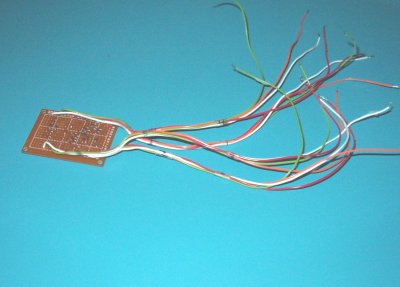
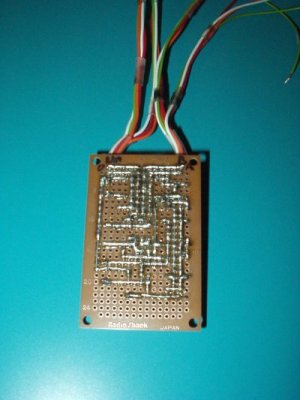
Here's what the board looks like, using the author's "solder blob" method. The wires were color selected for the standard resistor color code, relevant to the pin numbers on each DB connector. Then the wires were grouped into four bundles; one for each of the four ports. That way makes it real easy to identify the wires for the final install in a box, with the DB-25 (or 9) connectors, etc.


It's recommended testing the isolation for all four ports, that is pin 2 to 3, pin 5 to 20, for all the ports. Refer to the schematic, (Figure 3) above. Bring up the "large" version to see the diodes, relevant to the pin positions under "test". Use a good DVM/diode checker for this test. Three should show diode continuity, while it's own port will be isolated between these pin groups. Be sure your DVM has the proper polarity for diode checking; minus "voltage" should go towards the cathode of the diode (circuit) under test.

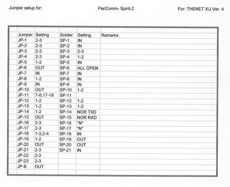
Also the club's stuff uses several differnt TNCs including a PacComm. In case you need to replace the Lit battery you can call them at (813) 874-2980. For the MFJ's battery uses type # CR2430. FYI
Now, if all of this is too much to pick up, you might try reading a document on the beginner's page, by clicking HERE
Back to SRG tech page ![[SRG home Direction]](images/srghome.gif)