Running two-cycle engine for modern snowmobiles
A two-cycle in its purest form is extremely simple in construction and operation, as it only has three primary moving parts (the piston, connecting rod, and crankshaft). However, the two-cycle cycle can be difficult for some to visualize at first because certain phases of the cycle occur simultaneously, causing it to be hard to tell when one part of the cycle ends and another begins.
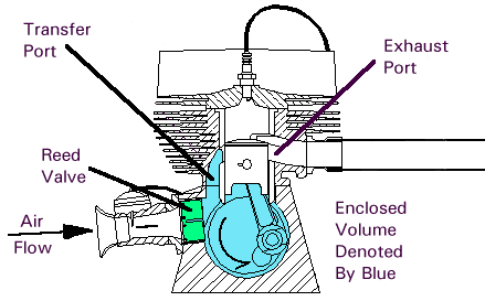
Several different varieties of two-cycles have been developed over the years, and each type has its own set of advantages and disadvantages. This one is known as a case-reed type because induction is controlled by a reed valve mounted in the side of the crankcase.
The easiest way to visualize two-cycle operation is to follow the flow of gases through the engine starting at the air inlet. In this case, the cycle would begin at approximately mid-cycle when the piston is rising, and has covered the transfer port openings:

As the piston moves upward, a vacuum is created beneath the piston in the enclosed volume of the crankcase. Air flows through the reed valve and carburetor to fill the vacuum created in the crankcase. For the purposes of discussion, the intake phase is completed when the piston reaches the top of the cycle (in reality, mixture continues to flow into the crankcase even when the piston is on its way back down due to the inertia of the fuel mixture, especially at high rpm):
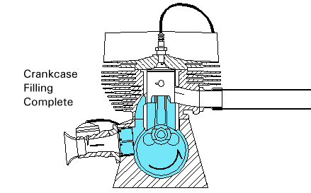
During the down cycle, the falling piston creates a positive pressure in the crankcase which causes the reed valve to close. The mixture in the crankcase is compressed until the piston uncovers the transfer port openings, at which point the mixture flows up into the cylinder. The engine depicted here is known as a loop-scavenged two-cycle because the incoming mixture describes a circular path as shown in the picture below. What is not readily apparent in the picture is that the primary portion of the mixture is directed toward the cylinder wall opposite the exhaust port (this reduces the amount of mixture that escapes out the open exhaust port, also known as short-circuiting):
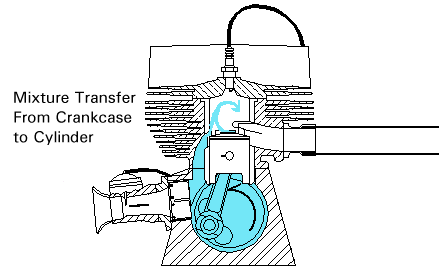
Mixture transfer continues until the piston once again rises high enough to shut off the transfer ports (which is where we started this discussion). Let's fast-forward about 25 degrees of crank rotation to the point where the exhaust port is covered by the piston. The trapped mixture is now compressed by the upward moving piston (at the same time that a new charge is being drawn into the crankcase down below):
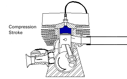
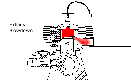
Somewhat before the piston reaches the top of the cycle (approximately 30 degrees of crank rotation before top-dead-center), the sparkplug ignites the mixture. This event is timed such that the burning mixture reaches peak pressure slightly after top dead center. The expanding mixture drives the piston downward until it begins to uncover the exhaust port. The majority of the pressure in the cylinder is released within a few degrees of crank rotation after the port begins to open:
Residual exhaust gases are pushed out the exhaust port by the new mixture entering the cylinder from the transfer ports.
That completes the chain of events for the basic two-cycle cycle. The discussion is not complete, however. The animated demonstration has an added device commonly known as an expansion chamber attached to the exhaust port. The expansion chamber (an improperly named device) utilizes sonic energy contained in the initial sharp pulse of exhaust gas exiting the cylinder to supercharge the cylinder with fresh mixture.
Picking up the discussion at the point shown by the exhaust blowdown picture above, an extremely high energy pulse of exhaust gas enters the header pipe when the piston begins to open the exhaust port:

The sonic compression wave resulting from this abrupt release of cylinder pressure travels down the exhaust pipe until it reaches the beginning of the divergent cone, or diffuser, of the expansion chamber. From the perspective of the sound waves reaching this junction, the diffuser appears almost like an open-ended tube in that part of the energy of the pulse is reflected back up the pipe, except with an inverted sign (a rarefaction, or vacuum pulse is returned). The angle of the walls of the cone determine the magnitude of the returned negative pressure, and the length of the cone defines the duration of the returning waves:

The negative pressure assists the mixture coming up through the transfer ports, and actually draws some of the mixture out into the exhaust header. Meanwhile, the original pressure pulse is still making its way down the expansion chamber, although a considerable portion of its energy was given up in creating the negative pressure waves. The convergent section of the chamber appears like a closed-end tube to the pressure pulse, and as such causes another series of waves to be reflected back up the pipe, except these waves are the same sign as the original (a compression, or pressure wave is returned). Notice that this cone has a sharper angle than the diffuser, so that a larger proportion of energy is extracted from the already weak pressure pulse:

This pulse is timed to reach the exhaust port after the transfer ports close, but before the exhaust port closes. The returning compression wave pushes the mixture drawn into the header by the negative pressure wave back into the cylinder, thus supercharging (a bigger charge than normal) the engine. The straight section of pipe between the two cones exists to ensure that the positive waves reaches the exhaust port at the correct time:

Since this device uses sonic energy to achieve supercharging, it is regulated by the speed of sound in the hot exhaust gas, the dimensions of the different sections of the exhaust system, and the port durations of the engine. Because of this, it is only effective for a very narrow rpm range. This explains why two-cycle motorcycles equipped with expansion chambers have such vicious powerbands (especially in the old days before variable exhaust port timing existed). With the design illustrated here (i.e. a single divergent stage and a single convergent stage), the powerband of the engine will be akin to a 'light switch' - once the expansion chamber goes into resonance, there will be a huge, almost instantaneous increase in power. The powerband can be softened somewhat by reducing the angles on the cones, but this is simply due to a lower degree of supercharging. In order to get the best of both worlds (a large power increase and a wide powerband), the cones should consist of several sections, with a different angle for each section. Proper design of even a simple expansion chamber is somewhat of a black art, even though formulae exist that will get you in the ballpark (there is quite a bit more to this than simply choosing the appropriate angles and lengths based on sonic velocity - everything about the pipe comes into play, including the headpipe diameter and length, and the tailpipe ('stinger') diameter and length). Design of a multi-stage expansion chamber becomes incredibly difficult - it basically comes down to the old 'cut and try' approach in the end. This of course is not even considering whether or not the exhaust and transfer port timings and outlet areas have been optimized for expansion chamber use.
Here is the animation showing the complete operation
