Coax lengths should be at least 102" and 42" for 2 and 1 1/4 meters respectively. This will be later. As a reminder, you can save the plans by right clicking and "save as". It's an Excel file.
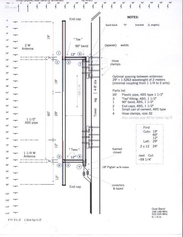
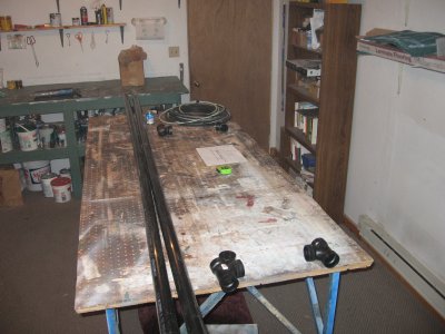
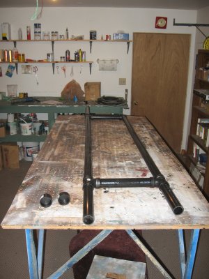
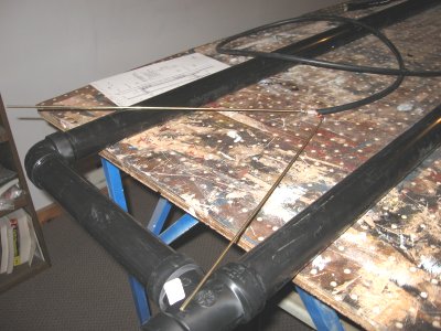
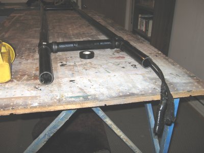
Start with laying out the parts. Seen here is the pipe, fittings, glue, drawing/plan, coax and measuring tape. Make you first three cuts;
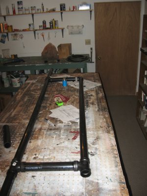
Shown here is most of the items laid out on the table Next, make your cuts of the pipe:
A 19"
A 60"
A 12"
That will make up 5 pieces. Then you should have about 29" left (assuming it's off a 10-foot stick) so you can make two more cuts being a couple of 12" pieces. Next per the drawing/plans glue each part in the order of the reference numbers on the drawing/plans. By doing this you'll have minimal impact on lining up the structure straight. Remember you'll only have about 5 seconds to insert each glued piece, before it starts to set up. If you make a mistake you'll have to start over with that section, or "splice" with a coupling, however this resort weakens the structure.
Steps 1-4 are simple. The import step is 5. By using the top section as a guide, immediately after gluing/inserting the lower "Tee" in step 5 lay the structure on the (flat) table to line up both 12" extender sections.
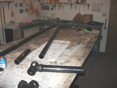
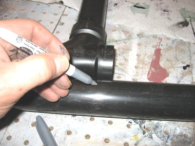
The rest is easy; continue with steps 6-7. Now (without gluing) insert the top 90° bend into the 12" extender section. This will line-up where you need to cut for the lower end of this pipe, as shown in the picture. Use the second 10-foot stick for this. Cut it, then glue that area (step 8), insert it and immediately insert (with no glue) the top pipe (with the 90* bend) into the top extender and hold it for a few seconds.
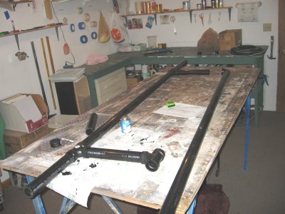
The bottom will set, and then you now can glue and insert the top bend (step 9) to permit easy alignment of the structure. This should get you within a ½" error between the two vertical sections, which is ample for this project. If you are a perfectionist, just add a little on the top extender so the two vertical sections are perfectly parallel. Whatever short piece you have lying around can be for step 10; since it does not affect anything but the pig tails.
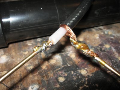
Next, build the two antennas. Cut the brass rods to make up 2 19" for the 2 meter and two 12" for the 1 ¼ meter antenna. Strip the coax ends for each band and solder them to the rods. Leave enough striped to allow some bending of the wires. The length of each coax is measure from each outer "Tee" (feed point) to follow inside the pipe (difference routes) and provide about a 12-18" pigtail out the bottom, inner pipe. Your final length will depend on what (scrap) length of pipe you choose to glue in the lower, inner "Tee" fitting (performed in step 10). 18" is a good all-around length to work with to connect to the station's line and tape it up. Shorted makes it difficult and longer needs to be tied up, away from ice loading.
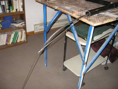
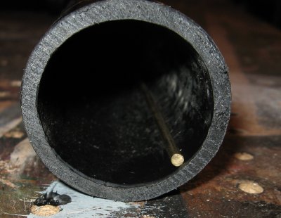
Next run a string down from the top end, take a turn at the first "Tee", then the second to allow it to exit out the bottom. Using a big nut or other weight makes this possible. Next tape the (connector) end of the coax and use the string to pull it through the pipe.
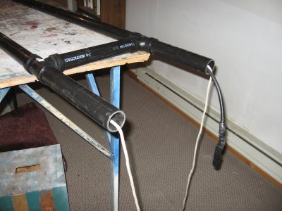
Repeat the same procedure for the bottom antenna, with the obvious bottom entry point, as seen in the picture. The right picture shows the top antenna pulled up to the pipe. Actually, this is a little too far as the next paragraph explains.
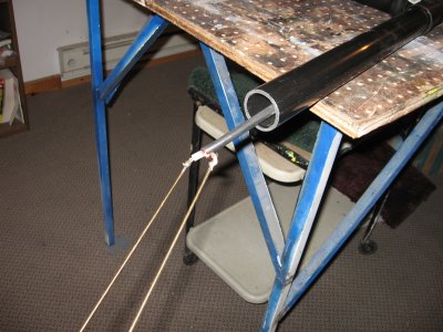
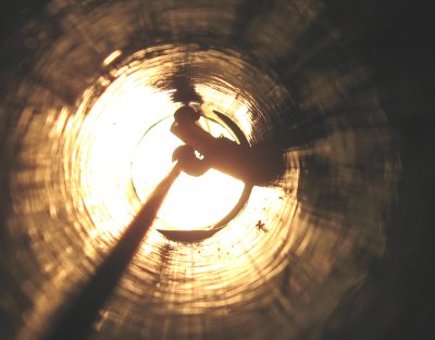
When the dipole starts to enter the top, bend sharply the lower radiator against the coax so all of it will fit inside the pipe. Continue to fish and pull it to the point of the feed point expanding inside the first "Tee". You can look down the pipe to see this. By pulling or pushing slightly you can adjust the feed point for a nice, mid-center position inside the pipe. This is also a good time to check for no shield whiskers getting too close to the hot side of the dipole.
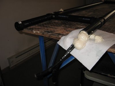
When you get done both pig tails will exit out the bottom, inside pipe. This would be a good time to test both antennas for any problems, since it's easy to remove something before sealing them up. The left picture was taken after the test, since the connectors are taped up. The top and bottom ends will have the end of the rod just about even with the openings. To help against the rods rattling in the breeze, stuff some foam padding inside the three openings, top, bottom and coax exit area.
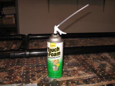
Another option is to secure the rods and pig tails with expandable spray (insulation) foam. This will nicely protect against the harsh weather and the summer insects/critters and has no known affect to RF signals. The foam comes in a spray can and is easy to apply. Shown here is the 3x (max) expanding in a 12 oz can. Shoot it up, inside the coax exit area and down the rod's ends. As shown in the right picture the foam will ooze out the bottom. The first reaction is to "clean it up" at that point. Don't; just leave the mess for a day or less. Same goes for any sticking/spilling/making a mess. In this state it's real gooey and messy to clean. If you wait for it to dry it's real easy to cut/chip off later. Later it's like a hard, burnt waffle.
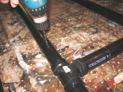
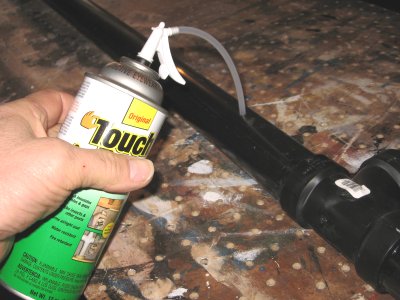
If you want to secure the feed points from rattling around here's a cool idea which the Author performed for Rx4 antenna in 2008. Drill a small hole just enough to get the spray tube inside. One hole around each feed point should do it. Shoot about 1/3 for each area; Top feed point, lower feed point and the coax exit area. Even the smaller 12 oz can should be enough. There will be a lot of pressure during expansion and some will come back out the little holes. The ABS should be strong enough to hold its shape and when it dries you can push a little RTV silicone in the holes to finish the weather seal.
When you are done with the foam glue you can install the top and bottom end caps. If you are careful you can install them while the foam is drying. After the caps are dry, the structure is ready for installation at the site.
Hose clamps are strong enough (when properly tightened in numbers) yet, are easy to install even while on a tower, alone in fowl weather.
Most hose clamp's screw tighter use a 5/16" nut driver.
For very long clamps (and screwing) you could use your cordless screwdriver with the proper adapter for that size.
It might be a good idea to check the size of bracket it will be mounted to; in many cases the hose clamps size # 32 will do.
This is true with a bracket that uses the
1 1/2" x 1 1/2" angle metal with a thickness of 1/8".
![[SRG home Direction]](images/srghome.gif)