Back to SRG tech page ![[SRG home Direction]](images/srghome.gif)
RF in a vacuum (or outer space) will go a long way because of little or no loss in the signal. This is partially from no "obstacles" from this condition. In the real world for terrestrial (land, point to point) LMR type communications (path) there is some "resistance" to the path. For one, air and other atmospheric gas has an effect on the RF. The signal will attenuate at an exponential rate. For example, most of the lost is notice the first few miles from the transmit point to the (far end) receiver point. As the path gets longer in the 50-100 mile range the lost still adds up, but at a lower rate.
Most (link) radio paths are in that area for large systems covering a large area for the users to enjoy such a system. For the far end receive signal to be reliable you need to have some "headroom" for protection with varying conditions in the real world, such as weather, temperature, etc. This headroom normally is call fade margin (FM). FM is the point of the (normal) received signal level (RSL) at the far end of a link, to the point that far end squelch's (or rejects) the RSL. For Amateur use this should be better than 20 db. SRG's spec is for 30 or better on main links.
Path calculation are done with figures. Figures with a "+" is an addition, while figure with a "-" is a subtraction. Here's how we can calculate this:
Originating transmit signal:
Transmitter power out........................................................................ +40 dbm
Station losses, such as duplex, isolator, filters, etc...................................... -2 db
Transmission line loss, from TOR (Top Of Rack) or cabinet to the antenna............. -2 db
Antenna gain................................................................................. +10 db
Effect Radiated Power (ERP).................................................................. +46 dbm
Next, you take all the losses (and gains) for the far end.
For a hundred mile path loss at 400 MHz will be around 136 db, depending on weather, terrain and a few other minor factors.
For this lessen we'll call it that.
Far end antenna gain.......................................................................... + 10 db
Far end line loss............................................................................ - 3 db
Far end RSL at the TOR or cabinet............................................................ - 83 dbm
Far end station losses, such as duplexer, filters, etc.. ...................................... -2 db
Far end RSL into its receiver................................................................. - 85 dbm
Far end receiver's squelch setting.............................................................- 115 dbm
Fade margin of this link (one way)........................................................... 30 db
As you can see what your minimum system requirements will be for a quality link.
This is assuming you have interference-free operation at the far end.
Site desense can be understood with the Receiver Desense document on this site
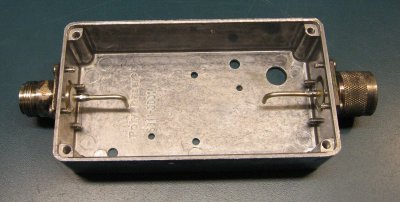
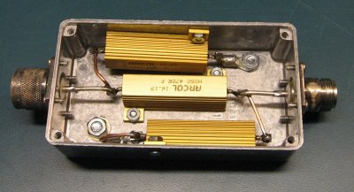
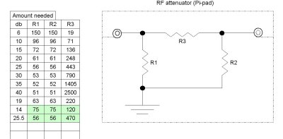
If you are alone and wish to measure the FM (Fade Margin) you can insert an attenuator in line with the transmitter, while monitoring the far end receiver. Here's a simple Pi pad. Common values of resistor where used therefore they end up with a non standard value, such as 14 db on one and 25 1/2 on the other. The Author built 2 of them each with a different value to use separately or used together.
Shown here is one of them; the stages of the build; with the holes drilled and the first wires positioned for the series resistor. The right image shows the completed attenuator with the top cover off. Back to SRG tech page